Introduction
As photovoltaic (PV) adoption accelerates, more projects are facing zero-export requirements. Utilities often prohibit excess solar power from flowing back into the grid, especially in areas with saturated transformers, unclear ownership of grid connection rights, or strict power quality rules. This guide explains how to install anti-reverse (zero-export) power meters, the core solutions available, and the right configurations for different PV system sizes and applications.
1. Key Considerations Before Installation
Mandatory Scenarios for Zero-Export
-
Transformer saturation: When local transformers are already operating at high capacity, reverse power may cause overload, tripping, or equipment failure.
-
Self-consumption only (no grid export permitted): Projects without grid feed-in approval must consume all generated energy locally.
-
Power quality protection: Reverse power may introduce DC components, harmonics, or unbalanced loads, lowering grid quality.
Pre-Installation Checklist
-
Device compatibility: Ensure the meter’s rated capacity matches the PV system size (single-phase ≤8kW, three-phase >8kW). Check inverter communication (RS485 or equivalent).
-
Environment: For outdoor installations, prepare weatherproof enclosures. For multi-inverter systems, plan for RS485 bus wiring or Ethernet data concentrators.
-
Compliance and safety: Confirm the grid connection point with the utility, and check that load range matches expected PV generation.
2. Core Zero-Export Solutions
Solution 1: Power Limiting via Inverter Control
-
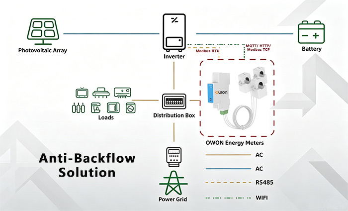
Principle: The smart energy meter measures real-time current direction. When reverse flow is detected, the meter communicates via RS485 (or other protocols) with the inverter, which reduces its output power until export = 0.
-
Use cases: Transformer-saturated areas, self-consumption projects with stable loads.
-
Advantages: Simple, low-cost, quick response, no need for storage.
Solution 2: Load Absorption or Energy Storage Integration
-
Principle: The meter monitors current at the grid connection point. Instead of limiting the inverter output, excess power is diverted to storage systems or dump loads (e.g., heaters, industrial equipment).
-
Use cases: Projects with highly variable loads, or where maximizing PV generation is a priority.
-
Advantages: Inverters stay in MPPT mode, energy is not wasted, higher system ROI.

3. Installation Scenarios by System Size
Single-Inverter Systems (≤100 kW)
-
Configuration: 1 inverter + 1 bidirectional smart meter.
-
Meter position: Between the inverter AC output and the main breaker. No other loads should be connected in between.
-
Wiring order: PV inverter → Current Transformers (if used) → Smart power meter → Main breaker → Local loads / Grid.
-
Logic: The meter measures direction and power, then the inverter adjusts output to match load.
-
Benefit: Easy wiring, low cost, fast response.
Multi-Inverter Systems (>100 kW)
-
Configuration: Multiple inverters + 1 smart power meter + 1 data concentrator.
-
Meter position: At the common grid coupling point (all inverter outputs combined).
-
Wiring: Inverter outputs → Busbar → Bidirectional meter → Data concentrator → Main breaker → Grid/Loads.
-
Logic: The data concentrator collects meter data and distributes commands to each inverter proportionally.
-
Benefit: Scalable, centralized control, flexible parameter settings.
4. Installation in Different Project Types
Self-Consumption Only Projects
-
Requirement: No grid export allowed.
-
Meter position: Between inverter AC output and local load breaker. No grid connection switch is used.
-
Check: Test under full generation with no load — inverter should reduce power to zero.
Transformer Saturation Projects
-
Requirement: Grid connection permitted, but reverse power strictly forbidden.
-
Meter position: Between inverter output and grid connection breaker.
-
Logic: If reverse power is detected, the inverter limits output; as backup, breakers may disconnect to avoid transformer stress.
Traditional Self-Consumption + Grid Export Projects
-
Requirement: Export permitted, but limited.
-
Meter setup: Anti-reverse meter installed in series with the utility’s bidirectional billing meter.
-
Logic: The anti-reverse meter prevents export; only in case of failure does the utility meter record feed-in.
5. FAQs
Q1: Does the meter itself stop reverse flow?
No. The meter measures power direction and reports it. The inverter or controller executes the action.
Q2: How fast can the system react?
Typically within 1–2 seconds, depending on communication speed and inverter firmware.
Q3: What happens during network failure?
Local communication (RS485 or direct control) ensures continued protection even without internet.
Q4: Can these meters work in split-phase systems (120/240V)?
Yes, certain models are designed to handle split-phase configurations used in North America.
Conclusion
Zero-export compliance is becoming mandatory in many PV projects. By installing anti-reverse smart energy meters at the correct location and integrating them with inverters, dump loads, or storage, EPCs, contractors, and developers can deliver reliable, regulation-compliant solar systems. These solutions not only protect the grid but also maximize self-consumption and ROI for end-users.
Post time: Sep-07-2025