A 24V thermostat wiring system uses low-voltage 24VAC control circuits to connect a thermostat with heating and cooling equipment such as furnaces, air conditioners, and heat pumps. In a typical North American HVAC system, the thermostat does not directly power the heating or cooling equipment. Instead, it uses 24VAC control signals to tell the HVAC control board when to activate heating, cooling, the indoor fan, compressor stages, or heat pump functions.
Common thermostat terminals include R or Rc/Rh for 24VAC power, C for common, Y for compressor control, W for heating, G for the fan, and O/B for a heat pump reversing valve. More advanced systems may also use Y2, W2/AUX, or E for additional heating and cooling stages.
Understanding these terminals is the starting point for reading a 24V thermostat wiring diagram, replacing an existing thermostat, or determining whether a smart thermostat is compatible with an HVAC system.
Important: Thermostat wiring varies by HVAC equipment and control design. Always turn off HVAC power before working with thermostat wiring and follow the wiring documentation for the thermostat and HVAC equipment. Some installations may require a qualified HVAC technician or electrician.
What Is 24V Thermostat Wiring?
Most conventional residential and many light-commercial HVAC systems in North America use a 24VAC low-voltage control circuit.
The HVAC equipment normally contains a transformer that steps the incoming line voltage down to approximately 24VAC for the control circuit. The thermostat then works as part of this low-voltage control system.
When heating or cooling is required, the thermostat uses the appropriate control terminals to call for a specific HVAC function.
For example:
- R → W can initiate a heating call in a conventional system.
- R → Y can initiate compressor operation for cooling.
- R → G can call for indoor fan operation.
- Heat pump systems may additionally use O/B to control the reversing valve.
This is why a 24V thermostat should not be confused with a thermostat designed to directly switch 120V or 240V line-voltage heating equipment.
Before replacing a thermostat, the control voltage and HVAC system type should always be identified first.

Which Wire Is 24V on a Thermostat?
This directly answers one of the most common questions about 24V thermostat wiring.
The R terminal normally supplies 24VAC power from the HVAC transformer.
Depending on the HVAC system, you may encounter:
| Terminal | Typical Function |
|---|---|
| R | 24VAC power |
| Rc | 24VAC power from the cooling transformer |
| Rh | 24VAC power for heating |
| C | 24VAC common |
| Y / Y1 | First-stage compressor |
| Y2 | Second-stage compressor |
| W / W1 | First-stage heating |
| W2 | Second-stage heating |
| G | Indoor fan relay |
| O/B | Heat pump reversing/changeover valve |
| AUX | Auxiliary heat |
| E | Emergency heat |
For example, the OWON’s PCT5231 24VAC WiFi thermostat installation documentation identifies Rc as 24VAC power from the cooling transformer, Rh as 24VAC primary for heating, and C as 24VAC common. It also provides separate connections for Y/Y1, Y2, W/W1, W2/E, G and O/B.
The exact terminal configuration still depends on the HVAC system.
Where Does a Thermostat Get Its 24V Power?
The 24VAC control power normally originates from a transformer inside or associated with the HVAC equipment.
A simplified control path looks like this:
HVAC Transformer → R → Thermostat → Control Terminal → HVAC Control Board
The R wire supplies the 24VAC side of the control circuit to the thermostat.
The C wire, when used, provides the common side of the transformer circuit. Modern WiFi thermostats often require this continuous R-to-C power path because their displays, processors and wireless communication need power even when the HVAC equipment is not actively heating or cooling.
This is one reason the C-wire has become increasingly important in smart thermostat installations.
Understanding a 24V Thermostat Wiring Diagram
A thermostat wiring diagram should be interpreted by terminal function, not simply by wire color.
Although certain wire colors are commonly associated with particular functions, installers should verify the terminal labels on the existing thermostat and HVAC control board.
A useful rule is:
Identify the terminal first; use wire color only as a secondary reference.
Before disconnecting an existing thermostat, taking a clear photograph and labeling every wire can make replacement considerably safer and easier.
The PCT5231 installation procedure, for example, specifically instructs installers to photograph the existing wiring, identify whether the system is conventional or heat pump, and label the wires before disconnecting them.
Common 24V Thermostat Wiring Terminals Explained
R, Rc and Rh — 24VAC Power
These terminals supply the thermostat with low-voltage power.
Some systems use one R wire, while others may have separate Rc and Rh connections associated with cooling and heating transformers.
Do not assume that Rc and Rh should always be jumpered. Follow the thermostat manufacturer’s instructions for single- and dual-transformer systems.
For example, PCT5231 provides separate Rc and Rh terminals and its installation guide specifies different connections depending on whether the existing system has R, Rc, Rh, or combinations of these wires.
C — Common Wire
The C-wire completes the 24VAC power circuit and is commonly required by WiFi and smart thermostats.
A conventional powered smart thermostat installation often uses:
R + C = continuous thermostat power
However, the C terminal is not itself an additional heating or cooling command. Its main role is providing the common side of the 24VAC control power circuit.
Y / Y1 and Y2 — Compressor Control
Y or Y1 normally controls the first compressor stage.
A multi-stage system may additionally use:
Y2 = second compressor stage
These connections can appear in multi-stage air-conditioning systems as well as heat pump systems.
W / W1 and W2 — Heating Control
In a conventional furnace system:
- W/W1 typically controls first-stage heat.
- W2 typically controls second-stage heat.
Heat pumps require more careful interpretation because these terminals may instead be associated with auxiliary or alternative heat.
For this reason, installers should first determine whether the HVAC system is conventional or heat pump before transferring W/AUX connections.
G — Fan Control
The G terminal typically controls the indoor blower fan relay.
When the thermostat calls for fan operation, the G circuit tells the indoor equipment to operate the blower according to the HVAC system’s control configuration.
O/B — Heat Pump Reversing Valve
The O/B terminal is particularly important when identifying 24V heat pump thermostat wiring.
It controls the heat pump’s reversing or changeover valve.
The required O/B configuration depends on the HVAC equipment. Some heat pumps energize the reversing valve in cooling, while others energize it in heating.
Therefore, connecting the O/B wire is only part of installation—the thermostat must also be configured correctly for the equipment.
24V Thermostat Wiring for Conventional HVAC Systems
A conventional furnace and air-conditioning system may use terminals such as:
R / Rc — 24VAC power
C — Common
W / W1 — Heating
Y / Y1 — Cooling compressor
G — Fan
A multi-stage conventional system can add:
Y2 — Second-stage cooling
W2 — Second-stage heating
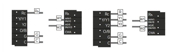
For example, the PCT5231 wiring documentation includes configurations for both conventional two-stage heating and conventional two-stage heating/two-stage cooling, illustrating how the number of control connections increases as HVAC staging becomes more complex.
This is an important consideration when replacing older thermostats: compatibility should be determined by HVAC functions and terminal requirements, not simply by counting the wires.
24V Heat Pump Thermostat Wiring
Heat pump wiring is generally more complex than basic furnace and air-conditioner wiring.
A typical heat pump installation may involve:
Rc/R — 24VAC power
C — Common
Y/Y1 — First compressor stage
Y2 — Second compressor stage
G — Fan
O/B — Reversing valve
AUX — Auxiliary heating
E — Emergency heating
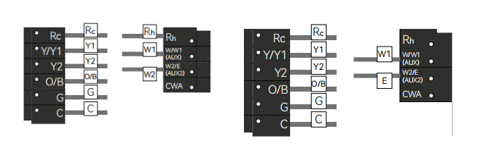
The PCT5231 documentation provides wiring examples for a two-stage heat pump with two-stage auxiliary heat and a two-stage heat pump with auxiliary and emergency heat.
This illustrates why a thermostat marketed simply as “24V compatible” is not automatically suitable for every 24VAC HVAC system.
The thermostat must also support the required:
- compressor stages,
- auxiliary heating stages,
- emergency heat,
- O/B operation,
- and equipment configuration.
What About Dual-Fuel 24V Thermostat Wiring?
Dual-fuel systems combine a heat pump with an alternative heating source, commonly a furnace.
Their thermostat requirements can therefore be more sophisticated than those of a basic single-stage system.
The thermostat may need to coordinate:
- Heat pump compressor stages
- O/B reversing valve
- Indoor fan
- Auxiliary or alternative heating stages
- Changeover between heat sources
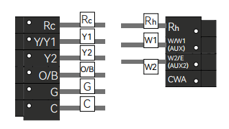
For example, the PCT5231 installation guide includes a wiring configuration for a dual-fuel system with a two-stage heat pump and two-stage heat, demonstrating the additional control connections involved in this type of installation.
For HVAC contractors and equipment manufacturers, this is why terminal compatibility and thermostat configuration should be evaluated together.
What If a 24V Thermostat Has Only Two Wires?
This deserves its own section because Google is specifically showing:
24v thermostat 2 wire wiring diagram
A two-wire thermostat commonly provides only a basic control path, such as a heating call.
That does not necessarily mean a modern WiFi thermostat can be connected directly to those same two wires.
A smart thermostat may require continuous 24VAC power through R and C, while the existing two-wire installation may not provide a C-wire or the other control connections required by the thermostat.
Therefore, before replacing a two-wire thermostat, verify:
- Whether the system actually uses 24VAC control.
- What the two existing terminals control.
- Whether a C-wire is available at the HVAC equipment.
- Whether additional wiring can be installed.
- Whether the thermostat supports an appropriate power adapter solution.
This is especially important in older heating-only installations.
What If There Is No C-Wire?
A missing C-wire is common in older HVAC installations.
The first step should be checking both the thermostat wiring and HVAC control board. An unused conductor may sometimes already exist in the thermostat cable.
If no usable C conductor is available, certain thermostat systems support a C-Wire Adapter.
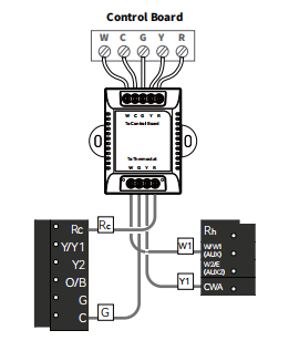
For example, PCT5231 requires a C-wire for power under its standard wiring configuration. Its installation guide provides an optional C-Wire Adapter method for compatible systems without an existing C-wire. The guide requires the necessary existing conductors and shows how the adapter interfaces with the HVAC control board and thermostat.
This is a good place in your website to internally link to your dedicated:
C-Wire / No C-Wire installation guide
rather than repeating the entire adapter installation procedure here.
Can You Connect a 24V Adapter Directly to a Thermostat?
This question corresponds closely to Google’s:
How to connect 24V adapter to thermostat?
The answer is:
Not automatically.
A thermostat’s R and C terminals may use 24VAC for power, but this does not mean that any external 24V adapter can simply be connected to them.
The correct method depends on:
- thermostat electrical design,
- HVAC transformer configuration,
- single- or dual-transformer architecture,
- thermostat terminal design,
- and manufacturer instructions.
Connecting an independent transformer incorrectly can create unwanted interaction between separate transformer circuits or damage equipment.
Therefore, an external 24V transformer should only be used when the thermostat manufacturer explicitly supports that wiring configuration.
This distinction is particularly important because a C-Wire Adapter is not necessarily the same thing as a generic external 24V transformer.
Is a 24V Thermostat Compatible with 120V or 240V Systems?
Not directly.
A thermostat designed for standard 24VAC HVAC control circuits should not be connected directly to line-voltage thermostat wiring.
During replacement, indicators such as:
110VAC
120VAC
240VAC
L1 / L2
can indicate a high-voltage thermostat system rather than standard 24VAC HVAC control wiring.
The PCT5231 installation guide explicitly instructs users to check for these high-voltage indicators during the compatibility check because such systems may not be compatible.
This is particularly relevant when users search for:
Convert 120V thermostat to 24V
Such a conversion is not simply a matter of replacing the wall thermostat. It may require additional control equipment and should be evaluated according to the HVAC/heating equipment design and applicable electrical codes.
24V Thermostat Wiring for Smart HVAC Retrofits
For HVAC contractors, property managers, system integrators and equipment manufacturers, thermostat replacement is not only a matter of matching wires.
A reliable retrofit assessment should consider:
1. Control Voltage
Confirm that the system uses compatible 24VAC thermostat controls.
2. HVAC Type
Identify whether the equipment is:
- Conventional furnace + AC
- Heat pump
- Multi-stage HVAC
- Dual fuel
- Boiler or other heating equipment
3. Required Control Terminals
Determine whether the application requires:
R/Rc/Rh, C, W1/W2, Y1/Y2, G, O/B, AUX or E.
4. Continuous Power
Determine whether a C-wire is available for the smart thermostat.
5. System Configuration
Correct wiring alone is not enough. The thermostat must also be configured for the actual equipment type, stages and heat pump operation.
This becomes particularly important in multifamily and light-commercial retrofit projects, where installers may encounter different HVAC configurations across a building portfolio.
Example: A 24VAC Smart Thermostat Wiring Platform
For example, OWON PCT5231 is designed for North American 24VAC HVAC applications and illustrates the type of terminal flexibility required for modern thermostat retrofit projects.
Its wiring architecture supports terminals including:
Rc, Rh, C, Y/Y1, Y2, W/W1 (AUX), W2/E (AUX2), G and O/B, with an optional C-Wire Adapter configuration for applicable installations without an existing C-wire. Its documented wiring examples include conventional multi-stage HVAC, heat pumps with auxiliary/emergency heat, and dual-fuel configurations.
For professional projects, the important takeaway is not simply whether a thermostat is “24V.” The thermostat’s terminal capacity, HVAC configuration options and actual equipment compatibility should all be reviewed before deployment.
Frequently Asked Questions About 24V Thermostat Wiring
Which wire is 24V on a thermostat?
The R, Rc or Rh connection normally carries the 24VAC supply from the HVAC transformer. C provides the common side of the 24VAC control circuit.
How does a 24V thermostat work?
A 24V thermostat uses a low-voltage HVAC control circuit to request heating, cooling, fan operation or other functions through terminals such as W, Y, G and O/B.
Where does the thermostat get power for the 24V controls?
The 24VAC control power typically comes from a transformer located inside or associated with the HVAC equipment. R supplies the thermostat side of the circuit, while C provides common when continuous thermostat power is required.
What is the C-wire on a 24V thermostat?
The C-wire is the common connection of the 24VAC control circuit. Smart thermostats commonly use R and C to obtain continuous operating power.
Can a 24V thermostat work with only two wires?
Some basic 24VAC heating controls can use two wires, but many WiFi smart thermostats require additional connections, particularly a C-wire or a supported power-adapter solution.
Is thermostat wire color standardized?
Wire colors often follow common conventions, but color alone should not be used to identify function. Verify the existing terminal labels and HVAC control-board connections before rewiring.
Final Thoughts
Understanding 24V thermostat wiring starts with identifying the HVAC control voltage and then matching each thermostat terminal to its actual equipment function.
For basic conventional systems, wiring may involve only R, C, W, Y and G. Multi-stage systems add terminals such as W2 and Y2, while heat pumps can introduce O/B, auxiliary heat and emergency heat controls.
For homeowners, this knowledge helps explain how a thermostat communicates with HVAC equipment. For contractors, system integrators and property operators, it is also essential for evaluating retrofit compatibility before deploying smart thermostats across multiple HVAC systems.
Most importantly, 24VAC compatibility alone does not guarantee thermostat compatibility. HVAC type, staging, terminal requirements, C-wire availability and system configuration should all be verified before installation.
Related reading:
If you are planning larger HVAC modernization projects beyond individual thermostat upgrades, you may also find this guide helpful:
Post time: Jan-26-2026


